
Current Version: Profex 5.5.1 - Released July 06, 2025

Introduction
The Rietveld refinement software must be able to precisely describe the measured peak shape with a mathematical model to obtain accurate fits of measured diffraction peaks. BGMN uses the fundamental parameters approach (FPA), and thus raytraces the peak shape from the diffractometer’s hardware configuration rather than fitting it to a measured reference pattern. Very detailed hardware information must be specified by the user in order to obtain a correct peak shape model. But in return, FPA peak shapes often describe strongly asymmetric peaks at very low diffraction angles more realistically and accurately than generic peak profile functions. FPA peak shapes can also be computed at any 2θ angle, whereas measured peaks of a reference material can only be fitted from the 2θ position of the first peak up. Extrapolation to lower angles introduces increasingly severe error.
Profex includes a set of hardware configuration files. But very often these configurations differ to a certain degree from configurations used by other users. Applying even a slightly wrong configuration file will result in poor quality of fits and most likely in wrong results. Using an instrument configuration file not specifically created for the instrument in use is thus strongly discouraged. This tutorial describes how to customize an instrument configuration file for one’s own use.
Creating the Configuration File
It is much easier to adapt one of the existing configuration files than to create a new file from scratch. Profex includes default files for instruments manufactured by Bruker, PANalytical, Rigaku, and Siemens, with various old and modern detectors and beam path configurations. Normally the type of instrument and some basic hardware information is given in the file name. For example „D8-…“ and „D2-…“ refers to Bruker D8 or D2 instruments, and „xpert-…“ and „cubix-…“ to PANalytical X’Pert or CubiX instruments. Often the file name also contains information about the divergence slit mode (fds = fixed divergence slit, ads = automatic divergence slit) and detector (xcel = PANalytical X’Celerator, pixcel = PANalytical PIXcel, LynxEyeXE = Bruker LynxEye XE etc.).
Step 1: Select and open an existing instrument configuration file
Start Profex and select „Instrument → Edit Configuration…“ from the menu:

The file dialog will open in the Device file database. Try to find a configuration file that matches your own configuration as closely as possible:
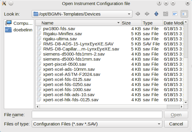
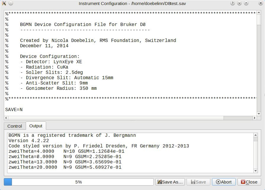
Open a file that seems to reasonably describe your own hardware. If none seems reasonable, open any arbitrary file. A dialog showing the content of the instrument configuration file will open:

Step 2: Edit the existing instrument configuration file
Most instrument configuration files start with a comment header with some information on the creator and instrument. Adapt this header to your own instrument.
Next you will have to go through the entire file line by line and make sure all parameters are set correctly for your own instrument. Change the parameters if necessary. If you don’t know some of the parameters, you will have to figure them out. Study the settings in your diffractometer control software, read the diffractometer manual, or take a ruler and measure the parameter at your instrument.
Instrument configuration files shipped with Profex are usually commented for easy comprehension. More information is given on the BGMN websites at http://www.bgmn.de/variables.html and http://www.bgmn.de/raytracing.html. All optical elements in the beam paths must be described accurately as described in the following schematic:
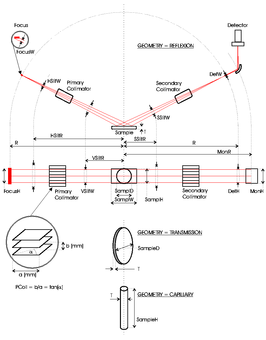
The opening of divergence and anti-scatter slits must be given in millimeters. However, for fixed slit configurations the opening is often specified in degrees as the angle of beam divergence. In that case, the slit width in mm can be calculated from the beam divergence angle and the position of the slit directly in the instrument configuration file. The relevant code section is shown below. This code can be used for all instruments using a fixed divergence or anti-scatter slit opening, if the slit opening is specified as beam divergence in degrees:
%------------------------------------------------------------------------
% Divergence slit
%------------------------------------------------------------------------

% beam divergence (degrees)
div=0.25

% distance from sample (mm)
HSlitR=100

% fixed divergence slit width (mm)
HSlitW=2*tan(div*pi/360)*(R-HSlitR)
For variable slit configurations, the opening of the divergence slit in mm changes as a function of the 2θ position. The slit width can also be calculated with the formula shown below. The same formula can be used for all instruments using variable slit width:
%------------------------------------------------------------------------
% Divergence slit
%------------------------------------------------------------------------

% irradiated length (mm)
irr=10

% distance from sample (mm)
HSlitR=100

% automatic divergence slit width (mm)
HSlitW=(2*(R-HSlitR)*irr*sin(pi*zweiTheta/360))/(2*R+irr*cos(pi*zweiTheta/360))
Once the file has been completely revised and all parameters have been matched to the user’s hardware configuration, you can save the file under a new name (ideally in the device file directory) using the „Save As…“ button. Give it a meaningful name, as with the default configuration files.
Step 3: Prepare the template file and run the calculation
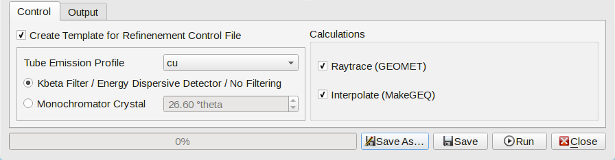
Before running the calculation, check the settings in the „Control“ tab below the text editor. Profex uses a template control file with each instrument configuration. An example will be shown later.
Go through the following steps:
- Activate the option „Create Template for Refinement Control File“
- Select the type of radiation your instrument uses („cu“ for characteristic copper radiation, „co“ for cobalt, „mo“ for molybdenum, „cr“ for chromium). Don’t use any of the other emission profiles unless you know what you are doing.
- Check whether your instrument uses a Kβ filter or monochromator crystal. In the latter case, specify the monochromator angle (the default of 26.60 degrees is correct for Graphite monochromators set up for CuKα radiation.)
- In the section „Calculations“ activate both options „Raytrace“ and „Interpolate“.
Step 4: Run the calculations
Now click „Run“ to start the calculation of the peak profiles and the interpolation. You may see a warning message:
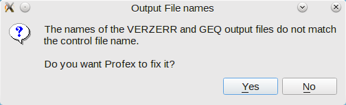
Profex suggests to fix it, so just click „Yes“. The message is shown because the variables „VERZERR“ and „GEQ“ at the beginning of the instrument configuration file were not changed to the new file name given in the „Save As…“ dialog.
Once the calculation started you will see some output information printed to the „Output“ console. The calculation takes several minutes, just wait for completion.
After completion, three new files have been created: <config-name>.ger, <config-name>.geq, and <config-name>.tpl. The *.tpl file is the template for the refinement control file Profex will use for each refinement project. It can be opened in a text editor:
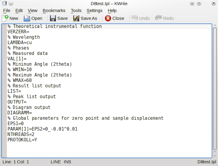
If any customizations for the specific instrument configuration shall be applied, it can be done in this template file. For example, WMIN and WMAX could be customized, or refinement of EPS1, EPS2 and EPS3. Or the intensity of Kα3 and Kβ could be specified. (See file cubix-ads-10mm.tpl for an example of Kα3 and Kβ.)
Step 5: Testing the configuration
The next time a new refinement project is created, the new instrument configuration will show up in the „Add/Remove Phase“ dialog’s dropdown box (here „D8test.geq“):

If the new configuration does not appear in the dropdown menu, make sure all four files <config-name>.sav, <config-name>.geq, <config-name>.ger, and <config-name>.tpl are stored in the device file directory, then restart Profex.
Device file directories are usually found in the following locations:
Windows:  ...\Profex-BGMN-Bundle\Profex\Devices
Mac OS X: .../Profex-Bgmn-Bundle/Devices
Linux:    unspecific
For Linux (optionally also for Windows and OS X), check „Edit → Preferences → BGMN → Device Files Directory“.
Nicola Doebelin, September 2016